

Serial I/O from a user program requires some extra caution. Please read the Serial Port Pitfalls appendix before using this block.


Placing Blocks and Lines
Flowcharts are constructed by placing new blocks and lines. To place a new object, select the appropriate tool from the Flowchart menu, Flowchart toolbar, or right-click context menu.
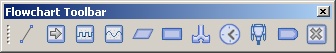
From left to right, these tools create:
- Line
- Start blocks
- Digital output blocks
- Analog output blocks
- Holding register blocks
- Variable blocks
- Conditional blocks
- Wait blocks
- Serial output blocks
- Modbus put blocks
- Stop blocks
Lines
Lines connect blocks and indicate the flow that execution will take. Lines always lead execution "into" a block at the top and lead execution "out of" a block at the bottom or side of a block. Don't worry about placing arrowheads on the lines. These will appear automatically.
After you select the line tool, the flowchart editor will enter the line-drawing mode. Use the mouse to position the cursor to where the line should start and click the mouse's left button. Then move the mouse to where the line should end and click the left mouse button again. Additional clicks will extend the line in a point-by-point fashion until the line reaches the socket on a block or another line.
To cancel the line-drawing mode, hit the F12 key or right-click with the mouse. If you have drawn some segments of a line, the final enpoint will be marked as a plug which can be connected later.
Start Blocks

Every flowchart should have one and only one start block, so there shouldn't be a need to place a new one unless you delete the original.
Start blocks are placed like any other block; select the start block tool, move the cursor to position the block where you would like it, and click the left button. To cancel the placing process, hit the F12 key or right-click the mouse.
The start block doesn't really do anything apart from mark the beginning of your program. Use the socket at the bottom of the start block to connect to the next block you want executed.
Digital Output Blocks
Digital output blocks control the RIO device's digital outputs. Each digital output block can set one digital output on or off.
Digital output blocks are placed like any other block; select the digital output block tool, move the cursor to position the block where you would like it, and click the left button. To cancel the placing process, hit the F12 key or right-click the mouse.
Once you place the block, the editor will pop up a dialog box where you can configure exactly what the block will do.
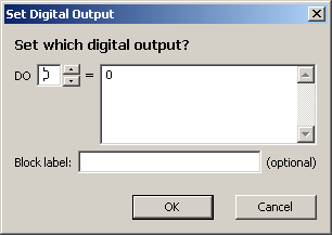
The configuration dialog allows you to select which digital output is set and to what value.
The spin-control in the dialog's upper-left sets which output will be set. Use 0 to set digital output DO1, 1 to set DO2, etc. The index number always begins counting at 0 for consistency with the C standard.
The large text-control in the dialog's upper-right sets the new value for the digital output. You can enter 1 to turn the output on, 0 to turn the output off, or even far more advanced expressions.
The text control at the bottom of the dialog lets you enter an optional label for the block. Labels are handy to clarify what the block is doing or to simplify the flowchart display when a complex value expression is involved. This label affects only the flowchart display, and not the program's operation.
Click OK to save your block configuration. This dialog can be edited later by double-clicking on the block.
When your program runs, execution will "enter" into the block from the socket at the top, then the digital output will be set as per your configuration, and then execution will "exit" out the socket at the bottom of the block.
Analog Output Blocks
Analog output blocks control the RIO device's analog outputs. Each analog output block can set one analog output to a given level.
Analog output blocks are placed like any other block; select the analog output block tool, move the cursor to position the block where you would like it, and click the left button. To cancel the placing process, hit the F12 key or right-click the mouse.
Once you place the block, the editor will pop up a dialog box where you can configure exactly what the block will do.
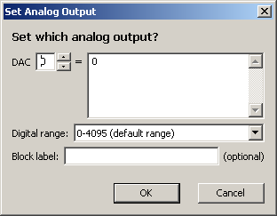
The configuration dialog allows you to select which analog output is set and to what value.
The spin-control in the dialog's upper-left selects which output will be set. Use 0 to set analog output AO1, 1 to set AO2, etc. The index number always begins counting at 0 for consistency with the C standard.
The large text-control in the dialog's upper-right sets the new value for the analog output. You can enter any value between 0 and the control's top range, or a more advanced expression.
In the middle of the dialog, you will find a drop-down range selector. This control will choose between the default range of 0-4095, and the extended ("D") range of 0-32767. Set this range to determine how the value expression will be interpretted.
The text control at the bottom of the dialog lets you enter an optional label for the block. Labels are handy to clarify what the block is doing or to simplify the flowchart display when a complex value expression is involved. This label affects only the flowchart display, and not the program's operation.
Click OK to save your block configuration. This dialog can be edited later by double-clicking on the block.
When your program runs, execution will "enter" into the block from the socket at the top, then the analog output will be set as per your configuration, and then execution will "exit" out the socket at the bottom of the block.
Holding Register Blocks
Holding register blocks allow you to set the value of three different categories of holding register; Xfer, Pulse, and Count registers. Each holding register block can set one holding register to a given value.
Holding register blocks are placed like any other block; select the holding register block tool, move the cursor to position the block where you would like it, and click the left button. To cancel the placing process, hit the F12 key or right-click the mouse.
Once you place the block, the editor will pop up a dialog box where you can configure exactly what the block will do.

The configuration dialog allows you to select which holding register is set and to what value.
The drop-down control in the dialog's upper-left sets which category of holding register will be set. The adjacent spin-control selects which register in the group will be set.
The large text-control in the dialog's upper-right sets the new value for the holding register. You can enter any value from 0-65535, or a more advanced expression.
The text control at the bottom of the dialog lets you enter an optional label for the block. Labels are handy to clarify what the block is doing or to simplify the flowchart display when a complex value expression is involved. This label affects only the flowchart display, and not the program's operation.
Click OK to save your block configuration. This dialog can be edited later by double-clicking on the block.
When your program runs, execution will "enter" into the block from the socket at the top, then the holding register will be set as per your configuration, and then execution will "exit" out the socket at the bottom of the block.
Variable Blocks

Variable blocks allow you to set the value of a user-defined variable. Each variable block can set one variable to a given value.
Variable blocks are placed like any other block; select the variable block tool, move the cursor to position the block where you would like it, and click the left button. To cancel the placing process, hit the F12 key or right-click the mouse.
Once you place the block, the editor will pop up a dialog box where you can configure exactly what the block will do.
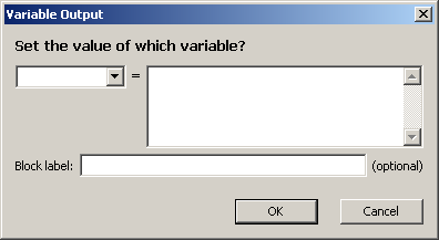
The configuration dialog allows you to select which variable is set and to what value.
The combo-box control in the dialog's upper-left selects the variable name to be set. You can enter a new variable name in from the keyboard or select a previously-defined variable from the drop-down portion of the control. Variables may be named any combination of letters, digits, and the underscore character ("_"), provided that the first character is not a digit.
The large text-control in the dialog's upper-right sets the new value for the variable. You can enter any value from 0-65535, or a more advanced expression.
The text control at the bottom of the dialog lets you enter an optional label for the block. Labels are handy to clarify what the block is doing or to simplify the flowchart display when a complex value expression is involved. This label affects only the flowchart display, and not the program's operation.
Click OK to save your block configuration. This dialog can be edited later by double-clicking on the block.
When your program runs, execution will "enter" into the block from the socket at the top, then the variable will be set as per your configuration, and then execution will "exit" out the socket at the bottom of the block.
Conditional Blocks
Conditional blocks allow you to branch execution in one of two directions depending on an expression known as a "condition". The directions (left/right/down) taken are configurable.
Conditionals are placed like any other block; select the conditional tool, move the cursor to position the block where you would like it, and click the left button. To cancel the placing process, hit the F12 key or right-click the mouse.
Once you place the block, the editor will pop up a dialog box where you can configure exactly what the block will do.
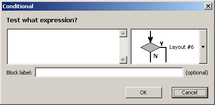
The configuration dialog allows you to enter the conditional expression and select the direction to go based on the result.
The large text-control in the dialog's left side sets the conditional expression. If the expression evaluates to "false" (0) then execution will follow the N path. A "true" (non-0) value will cause execution to follow the Y path.
The drop-down selector on the right side of the dialog selects which corners to assign the Y and N sockets. There are six possible combinations.
The text control at the bottom of the dialog lets you enter an optional label for the block. Labels are handy to clarify what the block is doing or to simplify the flowchart display when a complex value expression is involved. This label affects only the flowchart display, and not the program's operation.
Click OK to save your block configuration. This dialog can be edited later by double-clicking on the block.
When your program runs, execution will "enter" into the block from the socket at the top, evaluate the conditional expression you entered, and then "exit" out the appropriate socket based on the conditional value.
Wait Blocks
Wait blocks delay execution for a fixed amount of time. You can enter a time of as little as 1ms (0.001s) or as much as 60s.
Waits are placed like any other block; select the wait tool, move the cursor to position the block where you would like it, and click the left button. To cancel the placing process, hit the F12 key or right-click the mouse.
Once you place the block, the editor will pop up a dialog box where you can configure exactly what the block will do.
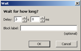
The wait dialog allows you to enter the delay amount. Use the two spin controls to enter the delay in seconds and milliseconds.
The text control at the bottom of the dialog lets you enter an optional label for the block. This label affects only the flowchart display, and not the program's operation.
Click OK to save your block configuration. This dialog can be edited later by double-clicking on the block.
When your program runs, execution will "enter" into the block from the socket at the top, wait for the specified amount of time, and then "exit" out the socket at the bottom of the block.
Serial Output Blocks
Serial output blocks allow you to output a string out the RIO device's serial port. This string will be sent to any serial device connected to the RIO; even a data radio. This is a handy mechanism for sending log messages or even commands to other devices.
Serial output blocks are placed like any other block; select the serial output block tool, move the cursor to position the block where you would like it, and click the left button. To cancel the placing process, hit the F12 key or right-click the mouse.
Once you place the block, the editor will pop up a dialog box where you can configure exactly what the block will do.
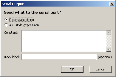
The configuration dialog allows you to set the string that will be output to the serial port.
The radio-buttons at the top of the dialog select whether the block will output a constant string or a string expression. The string expression option allows you to output variables or other numeric expressions in text form.
The large text-control in the dialog's middle sets the string to be output. If you have selected the constant string option, then the value in this box will be sent out the serial port exactly. If you have selected the C-style string expression option, then the text-control must contain a valid string expression that will be processed when the program's execution reaches the block.
The text control at the bottom of the dialog lets you enter an optional label for the block. Labels are handy to clarify what the block is doing or to simplify the flowchart display when a complex expression is involved. This label affects only the flowchart display, and not the program's operation.
Click OK to save your block configuration. This dialog can be edited later by double-clicking on the block.
When your program runs, execution will "enter" into the block from the socket at the top, then the string will be output over the RIO device's serial port, and then execution will "exit" out the socket at the bottom of the block.
Modbus Put Blocks
Modbus put blocks allow you to write a value to another Modbus device. Each Modbus put block can write to a single digital output or holding register.
Modbus put blocks are placed like any other block; select the modbus put block tool, move the cursor to position the block where you would like it, and click the left button. To cancel the placing process, hit the F12 key or right-click the mouse.
Once you place the block, the editor will pop up a dialog box where you can configure exactly what the block will do.
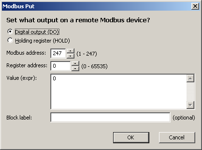
The configuration dialog allows you to select which register is written and to what value. From top to bottom, the controls are:
-
The radio buttons select whether the block will set a digital output (DO) or holding register (HOLD). Digital outputs are written with a "write single coil" (0x05) command. Holding registers aare written with a "write single register" (0x06) command.
-
The first spin-control selects the Modbus address to be targetted. Keep in mind that this is the address of the unit to receive the put and not the Modbus address of the RIO device executing the program. You cannot use this block to write to the device's local registers. See digital output and holding register blocks for that.
-
The next spin-control sets the register number that you wish to write.
-
The large text-control sets the value to be written. You can enter 0-65535, or more advanced expressions.
-
The last text control lets you enter an optional label for the block. Labels are handy to clarify what the block is doing or to simplify the flowchart display when a complex value expression is involved. This label affects only the flowchart display, and not the program's operation.
Click OK to save your block configuration. This dialog can be edited later by double-clicking on the block.
When your program runs, execution will "enter" into the block from the socket at the top, then the RIO will make up to three attempts to write the requested register, and then execution will "exit" out the socket at the bottom of the block.
Modbus output blocks set the Modbus error code. You can check this code after executing this block to determine whether the write completed successfully.
Stop Blocks

Unlike start blocks, stop blocks are optional. If execution reaches a stop block, then the program will end and no more program instructions will be executed until the RIO device is power-cycled or the program is re-run with the appropriate Modbus instructions.
Stop blocks are placed like any other block; select the stop block tool, move the cursor to position the block where you would like it, and click the left button. To cancel the placing process, hit the F12 key or right-click the mouse.
When your program runs, execution will "enter" into the block from the socket at the top, and then program execution will end. Execution will not "exit" from the block.
